Precision Boring: The Geometry Of Accuracy And Surface Integrity In Metal Machining
Release time:2026-07-03
Visits:109
In the hierarchy of metal cutting, boring occupies a distinct and critical position. Unlike turning or milling, which primarily generate external geometries, boring is the art and science of enlarging, finishing, and accurately locating existing holes. It is the definitive operation for achieving high-precision internal diameters (ID), straightness, and concentricity in components ranging from engine blocks to hydraulic valve bodies. This article explores the technical nuances, machine architectures, and process controls that define professional boring operations.
1. The Fundamental Principle: Removing Stock for Accuracy
At its core, boring is an internal turning operation. A single-point cutting tool (boring bar) is fed along the axis of a pre-existing hole (drilled, cored, or previously bored). The primary objectives are:
• Dimensional Accuracy: Achieving IT6 to IT7 tolerance grades (typically ±0.005 mm to ±0.01 mm).
• Geometric Integrity: Ensuring cylindricity, straightness, and perpendicularity of the bore axis.
• Surface Finish: Producing fine surface textures (Ra 0.8 – 3.2 μm) necessary for sealing, bearing fits, or fluid dynamics.
2. Machine Tool Architectures
The choice of boring machine dictates the scale and precision of the operation.
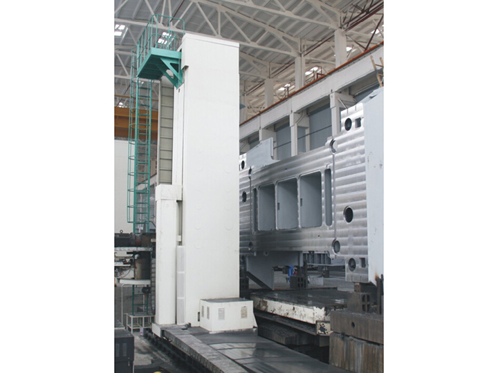
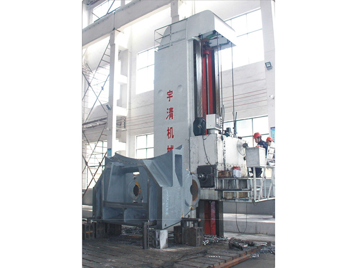
Horizontal Boring Mills (Table Type & Floor Type)
• Table Type: The workpiece is mounted on a moving table, while the spindle moves along the X-axis. Ideal for medium to large components (e.g., gearboxes, machine tool bases).
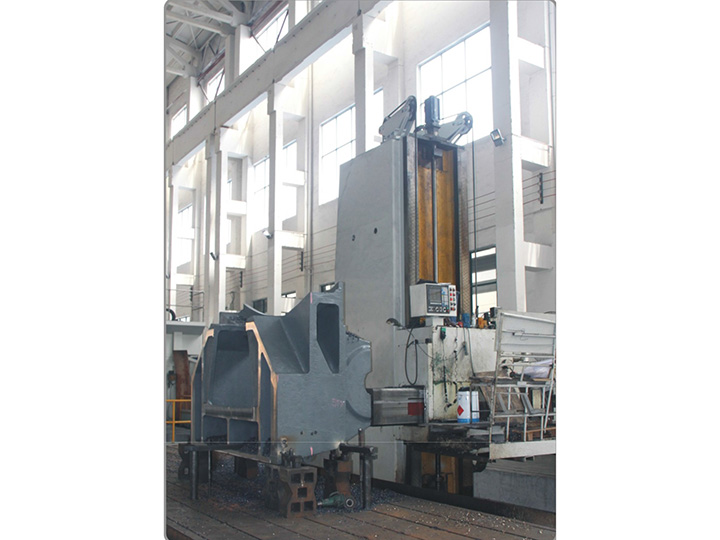
• Floor Type: The workpiece remains stationary on the floor plates, and the column/walking beam moves. Designed for massive fabrications like turbine casings or ship components.
Jig Borers
Historically significant, these are ultra-precision machines designed for locating holes with extreme accuracy (micrometer-level) in tooling and fixtures.
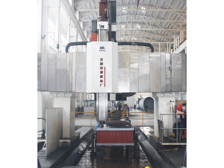
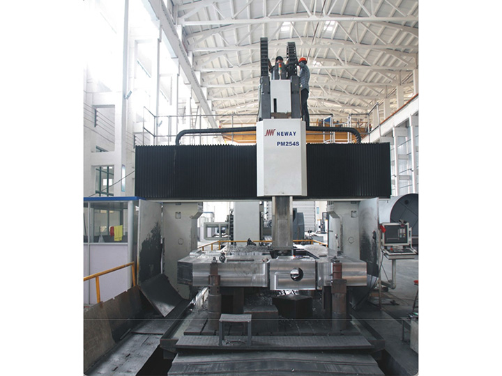
CNC Machining Centers (VMC/HMC)
Modern multi-axis machining centers
perform boring as part of a complete machining cycle. They utilize live tooling and rigid tapping capabilities for high-volume production.
3. The Cutting Tool System: Rigidity vs. Deflection
The success of a boring operation hinges on the tooling assembly, particularly the boring bar.
Boring Bar Type Material Composition Application Characteristic
Solid Carbide Micro-grain carbide Maximum rigidity for small diameters (<20mm); excellent for high-speed finishing.
Steel Shank (Brazed) High-speed steel or brazed carbide tip Cost-effective for general-purpose roughing; less rigid than solid carbide.
Modular Boring Heads Steel body with interchangeable carbide inserts Versatile for variable diameters; allows for fine adjustment (micron-level).
Anti-Vibration Bars Carbide with internal damping mechanisms Essential for deep hole boring (L/D ratio > 4:1) to suppress chatter.
Critical Challenge: Chatter and Deflection. As the length-to-diameter ratio increases, the boring bar acts as a cantilever beam, prone to vibration (chatter) and deflection. This leads to tapered holes, poor surface finish, and reduced tool life. Solutions include using the largest possible bar diameter, reducing overhang, and employing damped tooling.
4. Process Parameters and Optimization
Boring is typically divided into two phases:
1. Rough Boring:
◦ Objective: Remove the bulk of the material quickly.
◦ Parameters: Higher feed rates, moderate cutting speeds. Depth of cut is usually 2–5 mm per side.
◦ Consideration: Managing heat generation to avoid thermal expansion of the workpiece.
2. Finish Boring:
◦ Objective: Achieve final dimension, geometry, and surface finish.
◦ Parameters: Low feed rates, high cutting speeds. Depth of cut is minimal (0.1–0.5 mm).
◦ Consideration: Ensuring consistent chip evacuation to prevent recutting and surface damage.
5. Thermal Stability and Geometric Tolerancing
Precision boring is highly sensitive to temperature. A 1°C change in a cast iron component can alter a bore diameter by several microns. Professional shops maintain climate-controlled environments and allow machines and workpieces to reach thermal equilibrium before final measurement.
Furthermore, geometric dimensioning and tolerancing (GD&T) is essential. A bore is rarely specified by diameter alone. Requirements often include:
• Position (True Position): The location of the bore axis relative to datums.
• Perpendicularity: The squareness of the bore face to its axis.
• Cylindricity: The uniformity of the diameter along the entire depth of the hole.
6. Measurement and Quality Assurance
Verifying a bored hole requires more than a simple caliper.
• Bore Gauges (Dial/Digital): Used to measure internal diameter at various depths.
• Air Gauges: Provide high-resolution, non-contact measurement of diameter and taper.
• Coordinate Measuring Machines (CMM): The gold standard for verifying position, perpendicularity, and cylindricity in a 3D coordinate system.
Conclusion
Boring is a deceptively complex machining process. It demands a deep understanding of material behavior, machine dynamics, and metrology. Whether producing a high-pressure cylinder for a hydraulic system or aligning the main bearing journals in a marine diesel engine, the precision of the boring operation is often the limiting factor in the performance and longevity of the final assembly.