Why Is Weld Inspection the Last Line of Defense?
A weld that is not inspected is a weld whose quality is unknown. The shop may have qualified welders, qualified procedures, and good equipment — but the actual weld can still have defects that compromise strength, fatigue life, or pressure-tightness. Inspection is what turns the unknown into the known.
Inspection is also the legal evidence that the weld meets the specified standard. For regulated industries (pressure vessels, bridges, nuclear, oil & gas), the inspection record is what the regulator reviews. A missing record is a failing inspection.
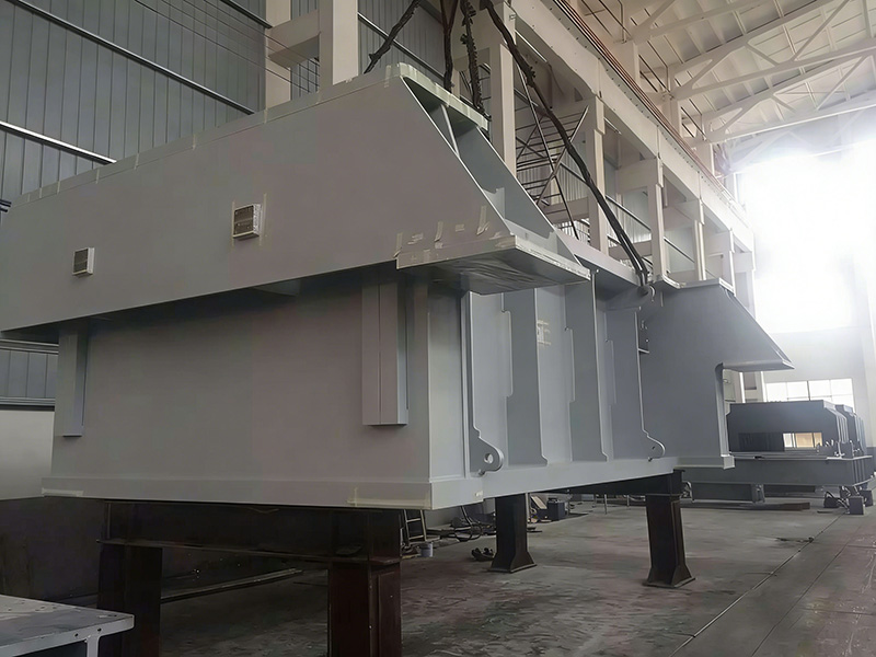
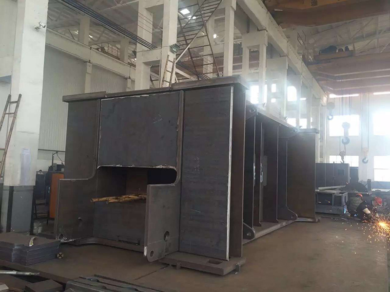
The processing of various weldments capability at Yuqing includes inspection to common standards; the engineer should specify which standard, which method, and which acceptance criterion.
What Are the NDT Methods?
|
Method |
Principle |
Detects |
Material |
|
Visual (VT) |
Eye or magnification |
Surface defects, profile, dimensions |
All |
|
Dye Penetrant (PT) |
Capillary action of dye |
Surface-breaking defects |
Non-porous (all metals, some plastics) |
|
Magnetic Particle (MT) |
Magnetic flux leakage |
Surface and near-surface defects |
Ferromagnetic only |
|
Eddy Current (ET) |
Electromagnetic induction |
Surface and near-surface defects |
Conductive only |
|
Ultrasonic (UT) |
High-frequency sound waves |
Subsurface and surface defects |
All |
|
Radiographic (RT) |
X-ray or gamma-ray absorption |
Internal defects |
All |
Each method has a defined scope, a defined sensitivity, and a defined limitation. The selection depends on the defect type of concern, the material, and the geometry.
What Is Visual Inspection (VT)?
Visual inspection is the first and most important NDT method. It catches the defects that any other method would also catch, plus many that the other methods would miss (profile, dimensions, fit-up).
A VT examination includes:
Pre-weld: verification of joint preparation, fit-up, cleanliness, and preheat.
In-process: verification of technique, parameters, and bead profile between passes.
Post-weld: verification of final profile, dimensions, surface defects, and marking.
VT requires:
Adequate lighting (1000 lux for general, 500 lux minimum at the inspection surface).
The inspector to have normal or corrected vision (verified annually).
The inspector to have appropriate training and qualification (AWS CWI, ASNT Level II in VT, or equivalent).
VT is the only NDT method that examines the joint preparation. A poor joint preparation cannot be corrected by a good weld; VT catches it before welding begins.
What Is Dye Penetrant Inspection (PT)?
Dye penetrant inspection uses a liquid dye that penetrates into surface-breaking defects. The surface is cleaned, the dye is applied, excess dye is removed, a developer is applied to draw the dye out of the defect, and the surface is inspected under appropriate lighting.
PT detects:
Surface cracks (fatigue, stress corrosion, hydrogen).
Surface porosity.
Surface laps and folds.
Lack of fusion at the weld surface.
PT does not detect:
Subsurface defects (use UT or RT).
Defects in porous materials (use VT or RT).
PT requires:
A clean surface (free of oil, paint, or other contaminants that could mask defects).
Sufficient dwell time for the dye to penetrate (typically 10–30 minutes).
Inspection under UV-A light for fluorescent penetrant, or white light for visible dye.
A trained and qualified inspector (ASNT Level II in PT, or equivalent).
PT is the standard for stainless steel, aluminum, and other non-ferrous materials. It is sensitive and relatively inexpensive, but requires careful surface preparation.
What Is Magnetic Particle Inspection (MT)?
Magnetic particle inspection magnetizes the part and applies iron particles (dry powder or wet suspension). Defects that interrupt the magnetic flux cause the particles to, revealing the defect as a visible indication.
MT detects:
Surface cracks.
Near-surface defects (up to ~6 mm below the surface).
Lack of fusion, lack of penetration.
MT does not detect:
Subsurface defects beyond ~6 mm (use UT or RT).
Defects in non-ferromagnetic materials (PT or ET instead).
MT requires:
A magnetizable material (steel, iron).
A magnetization method (yoke, coil, prod, or central conductor).
Inspection under visible or UV-A light.
Demagnetization after inspection if residual magnetism would affect service.
MT is faster than PT for steel parts and detects slightly deeper defects. It is the standard for ferromagnetic welds in structural and pressure vessel applications.
What Is Ultrasonic Inspection (UT)?
Ultrasonic inspection sends high-frequency sound waves (typically 2–10 MHz) into the part and analyzes the reflections from internal interfaces. Defects reflect sound differently than sound metal, producing indications that can be measured for size and location.
UT detects:
Subsurface cracks.
Lack of fusion.
Lack of penetration.
Porosity (though less sensitively than RT).
Lamellar defects in plate.
UT does not detect:
Very thin defects oriented parallel to the sound beam (must scan from multiple angles).
UT requires:
A trained and qualified inspector (ASNT Level II in UT, or equivalent per ISO 9712).
A couplant (gel, water, or oil) to transmit sound into the part.
Calibration on a reference block with known reflectors.
Access to both sides of the weld (in some cases).
UT is the standard for thick-section welds (over ~10 mm) and for critical welds where subsurface defects are of concern. It is faster than RT but requires more operator skill.
What Is Radiographic Inspection (RT)?
Radiographic inspection uses X-rays or gamma-rays to expose a film or digital detector. The radiation passes through the part; defects attenuate the radiation differently than sound metal, producing dark or light indications on the film.
RT detects:
Internal porosity.
Internal slag inclusions.
Lack of fusion.
Lack of penetration.
Cracks (with proper orientation).
RT does not detect:
Surface defects unless the radiation enters at a favorable angle.
Very thin laminar defects.
RT requires:
A licensed radiographer (per applicable regulation).
Radiation safety procedures and monitoring.
A controlled area during exposure.
Time for film development or digital processing.
RT is the standard for critical welds in pressure vessels, pipelines, and nuclear components. It produces a permanent record (the radiograph) that can be re-examined later. The cost and the radiation safety requirements make it less common than UT for general fabrication.
How Are Acceptance Criteria Defined?
Acceptance criteria are defined by the applicable standard. The criteria specify the maximum allowable defect size, type, and distribution.
AWS D1.1 acceptance criteria for statically loaded welds (typical):
|
Defect |
Acceptance |
|
Crack |
Not permitted |
|
Lack of fusion |
Not permitted |
|
Lack of penetration (CJP groove) |
Not permitted |
|
Undercut |
≤ 0.5 mm deep for ≤ 6 mm thickness; ≤ 1 mm for thicker |
|
Porosity (CJP groove) |
Total projected length ≤ 10 mm in 25 mm of weld; maximum 4 mm per indication |
|
Slag inclusion (CJP groove) |
Total length ≤ 10 mm in 300 mm; maximum 3 mm per indication |
|
Crater crack |
Not permitted |
ASME Section IX / Section VIII acceptance criteria are similar but have specific differences. ISO 5817 (for fusion welds) defines three quality levels (B, C, D) with progressively tighter acceptance.
The drawing should specify the standard and the quality level. A drawing that says "weld per AWS D1.1" applies the default acceptance criteria.
What Is the Inspection Sequence?
A typical inspection sequence:
Pre-weld VT: joint preparation, fit-up, cleanliness, preheat.
In-process VT: technique, parameters, bead profile.
Post-weld VT: profile, dimensions, surface defects, marking.
PT or MT: surface and near-surface defects (per the standard).
UT or RT: subsurface defects (per the standard, for critical welds).
Mechanical testing: for procedure qualification, not for production welds.
The sequence is defined by the standard. Skipping a step is not acceptable unless the standard allows it explicitly.
What Is the Inspection Extent?
The inspection extent is the percentage of welds examined and the percentage of each weld examined.
Typical extents:
|
Service |
VT |
NDT |
Extent |
|
Structural building |
100% |
10–25% |
Per AISC or AWS D1.1 |
|
Pressure vessel |
100% |
100% (UT or RT) |
Per ASME Section VIII |
|
Pipeline |
100% |
100% |
Per API 1104 |
|
Bridge |
100% |
100% |
Per AWS D1.5 |
|
Nuclear |
100% |
100% (multiple methods) |
Per ASME Section III |
|
General fabrication |
100% VT, sample NDT |
Per agreement |
Custom |
The drawing or the contract should specify the extent. A "sample" inspection without a defined percentage is ambiguous.
How Is an Inspector Qualified?
An NDT inspector is qualified by:
Formal training (40+ hours per method, depending on the standard).
Documented experience (months to years, depending on the method and level).
Examination (general and specific, per ASNT or ISO 9712).
Certification by the employer (for Levels I and II) or by an independent body (for Level III).
Certification levels:
Level I: works under the supervision of a Level II or III; performs specific calibrations and inspections.
Level II: performs and supervises inspections; certifies results; trains Level I.
Level III: establishes procedures; trains and examines Levels I and II; audits the inspection program.
For critical work, the inspector's qualification must be current and matched to the method, the material, and the applicable standard.
How Are Inspection Records Maintained?
A defensible inspection record includes:
Inspector name and qualification.
Inspection date and time.
Identification of the weld (drawing reference, weld number, location).
Method used (VT, PT, MT, UT, RT).
Procedure reference (the NDT procedure used).
Equipment used (with calibration reference).
Results (acceptable, reject, repair).
Indication sketches or radiographs (for NDT).
Inspector signature and supervisor countersignature.
Records are retained for the service life of the component (often 30+ years for pressure vessels and nuclear) and are available for audit by the regulator or the buyer.
What Is a Weld Map?
A weld map is a drawing that identifies each weld on the fabricated assembly by a unique number and indicates the inspection status.
The weld map:
Assigns a unique identifier to each weld (e.g., W-101, W-102).
Records the welder (or the welder's qualification reference).
Records the date of welding.
Records the inspection method and the result.
Tracks the rework or repair history.
The weld map is the link between the physical fabrication and the documentation. A fabrication without a weld map is a fabrication that cannot be traced, audited, or maintained.
What Is Weld Repair?
A weld that fails inspection is repaired by:
Removing the defect (by grinding, gouging, or re-cutting).
Cleaning the area.
Re-welding per the original WPS (or a qualified repair procedure).
Re-inspecting per the original inspection method.
Repair welds are documented in the same way as original welds. The repair history becomes part of the component's permanent record.
A weld that fails inspection repeatedly is a sign of a process problem (wrong parameters, wrong procedure, wrong welder). The root cause must be investigated, not just the symptom.
How Is Surface Profile Evaluated?
Surface profile (weld reinforcement, undercut, overlap) is evaluated visually:
Reinforcement: the height of the weld crown above the base metal. Usually limited to 1–3 mm depending on the standard.
Undercut: a groove at the weld toe. Limited to 0.5–1 mm deep depending on the standard.
Overlap: weld metal flowing over the base metal without fusion. Limited or not permitted depending on the standard.
The profile affects fatigue life (rough profile = stress concentration = reduced fatigue life) and corrosion resistance (crevices trap moisture).
How Is Weld Dimensional Accuracy Verified?
Weld dimensional accuracy includes:
Throat thickness: the minimum distance from the root of the weld to the face. Verified with a weld gauge.
Leg length: the length of the sides of a fillet weld. Verified with a weld gauge.
Length: the length of the weld along the joint. Verified by measurement.
Position: the location of the weld in the assembly. Verified by measurement against the drawing.
A weld that is too small (insufficient throat) fails the strength requirement. A weld that is too large wastes filler metal and may cause distortion.
What Is the Trend in Weld Inspection?
The trend is toward:
Phased array UT (PAUT): electronic scanning of multiple angles, faster and more accurate than conventional UT.
Time-of-flight diffraction (TOFD): precise sizing of defects through the wall thickness.
Digital radiography (DR): real-time imaging, no film processing, easier archival.
Computed radiography (CR): phosphor plate imaging, easier than film.
Automated visual inspection: cameras and AI algorithms for surface defect detection.
Welding inspection drones: for hard-to-reach welds in large structures.
The trend supports the same objective: more reliable inspection, more documented evidence, and faster turnaround.
Conclusion
Weld quality inspection is the engineering discipline that verifies the weld meets the specified standard, using the appropriate NDT method, by a qualified inspector, with documented results. The selection of VT, PT, MT, UT, or RT depends on the material, the defect type of concern, and the applicable code. The processing of various weldments and workshop capabilities at Yuqing support inspection to common standards; engineers should specify the method, the extent, and the acceptance criteria explicitly so the shop can plan the inspection and the buyer can verify the result.
Frequently Asked Questions
What is the most common NDT method for welds?
Visual testing (VT) is the most common — every
weld is inspected visually. For subsurface defects, ultrasonic testing (UT) is the most common for steel and stainless; radiographic testing (RT) is used for the most critical applications.
What is the difference between PT and MT?
PT uses a liquid dye that penetrates surface-breaking defects. MT uses magnetic particles attracted to flux leakage at defects. PT works on all metals and some plastics; MT works only on ferromagnetic materials. PT is more sensitive to very tight cracks; MT can detect slightly deeper defects.
When is RT used instead of UT?
RT is used when the inspection must produce a permanent image (the radiograph) for archival or for legal evidence. UT is faster, more portable, and uses no radiation. For most non-critical applications, UT is preferred.
How are acceptance criteria applied to welds?
The applicable standard (AWS D1.1, ASME Section VIII, etc.) defines the acceptance criteria for each defect type. The inspector measures the defect, compares to the criteria, and dispositions it as acceptable, repairable, or scrap.
What is phased array UT?
Phased array UT (PAUT) uses an electronically controlled array of transducers to steer and focus the sound beam. It scans multiple angles in a single pass, producing detailed images of the weld. PAUT is faster and more accurate than conventional UT, especially for thick welds.
How is NDT performed on a welder's qualification test?
The test weld is inspected by VT and NDT (typically RT or UT) per the qualification standard. The test plate is then mechanically tested (tensile, bend, impact) to verify strength and toughness. The combined visual, NDT, and mechanical results determine whether the WPS is qualified.
What is the role of the CWI?
A Certified Welding Inspector (CWI), certified by AWS, is qualified to inspect welds and verify conformance to AWS D1.1 and similar codes. For critical work, the CWI's signature is the legal evidence that the weld has been inspected and accepted.
What is the difference between PT and DPT?
PT (Penetrant Testing) is the general term. DPT (Dye Penetrant Testing) is the same method using visible dye. FPT (Fluorescent Penetrant Testing) uses fluorescent dye and UV-A light. FPT is more sensitive than DPT.
What is the typical extent of NDT for a structural weld?
Per AWS D1.1, the typical NDT extent for statically loaded structural welds is 10% of welds (ultrasonic or magnetic particle). For cyclically loaded welds (bridges, cranes), the extent is higher. The contract or the drawing specifies the extent.
How is a weld that fails inspection repaired?
The defect is removed (by grinding, gouging, or re-cutting). The area is cleaned. The weld is repaired per the original WPS (or a qualified repair procedure). The repair is re-inspected per the original method. The repair is documented in the weld map and the inspection record.