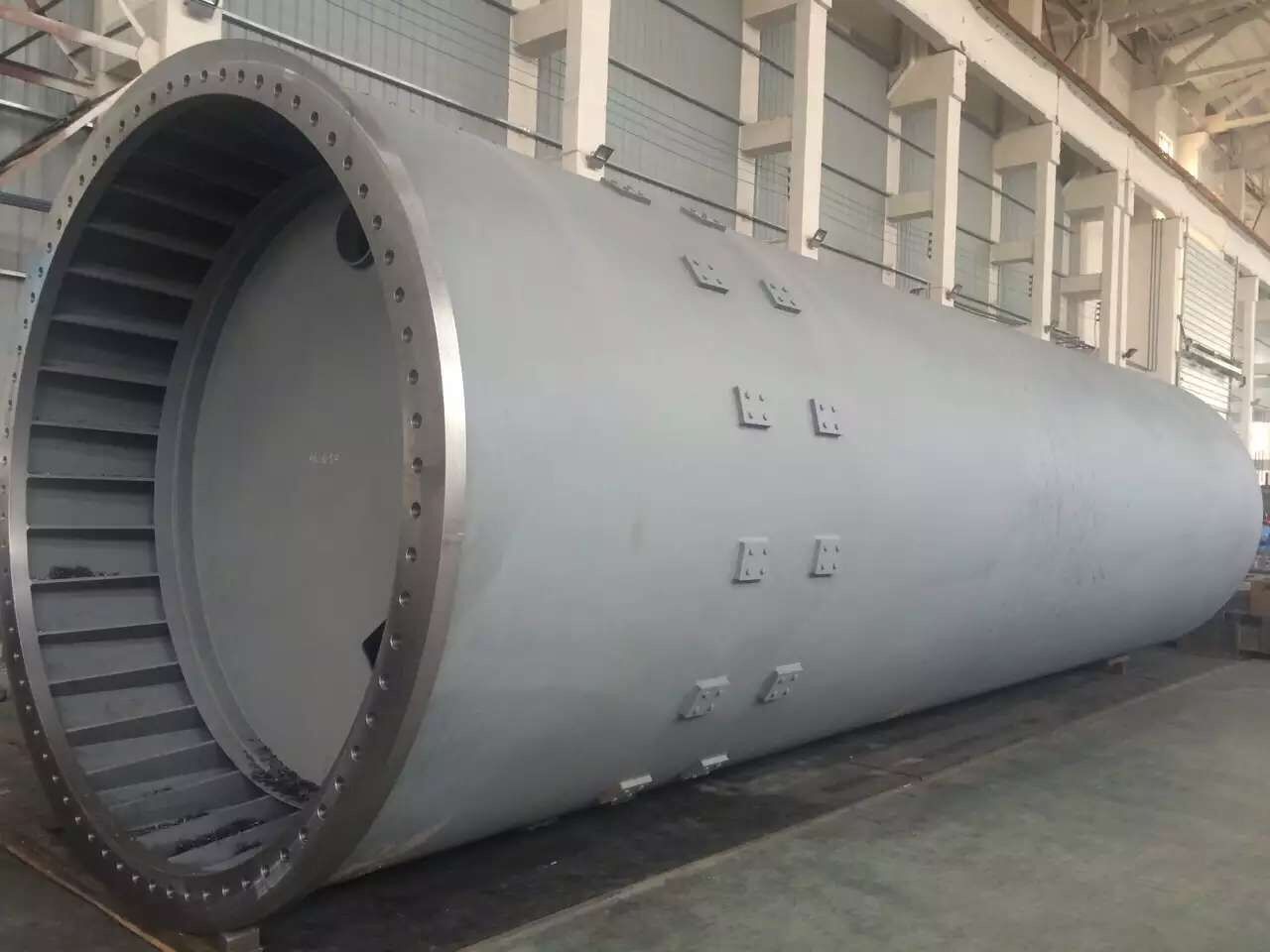
What Is DFM and Why Does It Matter for Custom CNC Machining?
DFM is the practice of designing parts with the manufacturing process in mind. For custom CNC machining, the manufacturing process is multi-axis milling, turning, boring, gantry, and complementary operations such as welding and inspection. Each process has capabilities, preferred feature geometries, and cost structures. A drawing that ignores those realities produces parts that are difficult or impossible to machine, expensive to quote, and prone to rejection at first article.
DFM is not about making parts easier to machine at the expense of function. It is about ensuring that every feature is machinable, every tolerance is achievable, and every specification is verifiable, without paying for capability the function does not need. The output of DFM is a drawing that is at the same time functional, manufacturable, and inspectable.
Yuqing's CNC machine tool processing capability covers multi-axis milling, turning, boring, and gantry. A part designed with that capability in mind — pocket depths matched to available tooling, hole patterns matched to standard tap sizes, corner radii matched to standard end mills — is a part that the shop can produce efficiently.
Design for the Standard Machining Process
The first DFM rule is to design for the standard process, not the exception. Every shop has a standard process library: the machine tools it runs, the tool library it carries, the workholding it prefers, and the inspection equipment it uses. A drawing that fits within that library is fast to quote, fast to set up, and fast to produce. A drawing that steps outside the library triggers custom tooling, custom workholding, custom inspection, and often a longer lead time.
Standard process elements to design around:
Standard tool diameters (e.g., end mills in 1 mm increments from 3 mm to 25 mm, drills in 0.5 mm increments from 1 mm to 30 mm).
Standard thread sizes (M3, M4, M5, M6, M8, M10, M12, M16, M20) rather than non-standard pitches.
Standard chamfers and edge breaks (0.5 × 45°, 1.0 × 45°, 1.5 × 45°).
Standard surface finishes (Ra 0.8, 1.6, 3.2, 6.3 µm) rather than exotic values.
Custom tooling is not prohibited; it is a deliberate choice that should be justified by the function it serves. A drawing that requests 23 standard features and 1 custom feature is generally fine; a drawing that requests 1 standard feature and 23 custom features signals that the designer has not engaged with the shop.
Choose the Right Material for Manufacturability
Material selection is a DFM decision, not a downstream one. The material drives tooling choice, cutting parameters, fixturing strategy, and achievable tolerances.
|
Material |
Machinability |
Tolerance Achievable |
Notes |
|
Aluminum 6061 |
Excellent |
IT8–IT9 |
Best for prototypes and complex geometries |
|
Steel 1018 |
Good |
IT9–IT10 |
Common for structural parts |
|
Steel 4140 |
Moderate |
IT8–IT9 after anneal |
Heat-treatable, distorts if not stress relieved |
|
Stainless 304 |
Moderate |
IT9–IT10 |
Work-hardens; use sharp tools and lower speeds |
|
Stainless 316 |
Moderate |
IT9–IT10 |
Similar to 304; better corrosion resistance |
|
Brass C360 |
Excellent |
IT7–IT8 |
Free-machining; ideal for precision turned parts |
|
Cast iron GG25 |
Good (dry) |
IT9–IT10 |
Abrasive; carbide tooling required |
|
Engineering plastic POM |
Excellent |
IT10–IT12 |
Low cutting forces, low heat, but soft |
Choose the material that meets the functional requirement with the lowest manufacturing risk. Aluminum 6061 is over-specified for many applications; steel 1018 is the workhorse for structural parts; stainless is reserved for corrosion or hygiene applications.
Yuqing's processing of various structural parts covers carbon steel, alloy steel, stainless steel, and aluminum, with documented capability for each material class.
Standardize Features and Geometry
The third rule is to standardize features. Standardization reduces tooling inventory, reduces setup time, and reduces programming time.
Examples of standardization:
Use one fillet radius (e.g., R3) for all internal corners of a pocket, not three different radii.
Use one thread size (e.g., M6) for all tapped holes that serve similar functions, not three different sizes.
Use one chamfer size (e.g., 1 × 45°) for all edges of a part, not a mix of chamfers and radii.
Use hole patterns based on standard grid spacing (e.g., 25 mm, 50 mm) rather than arbitrary spacing.
Use one surface finish (e.g., Ra 3.2 µm) for all machined surfaces, except where function requires a finer finish.
Standardization does not constrain the design. It constrains the manufacturing options to the set the shop runs every day, which is exactly what makes a quote predictable.
Specify Tolerances That Match Function
Tolerances should be as loose as the function allows and as tight as the function requires. The drawing should call out tolerances explicitly only where the general tolerance is insufficient.
|
Feature |
Typical General Tolerance |
When to Tighten |
|
Linear dimension |
ISO 2768-mK (±0.1 mm at small sizes, ±0.2 mm at large) |
Mating fit, sealing surface, bearing seat |
|
Hole diameter |
ISO 2768-mK |
Press fit, fastener clearance |
|
Surface profile |
Not specified |
Sealing surface, dynamic load surface |
|
Position |
ISO 2768-mK |
Mating pattern, assembly reference |
|
Angular |
±0.5° |
Mating angle, sealing surface |
Tightening a tolerance without a function to justify it is a DFM violation. The cost of tight tolerances — slower cutting, additional inspection, higher scrap — is paid for every part, every time.
Yuqing's processing of mechanical parts capability is documented against ISO 2768 general tolerances. Designers can rely on the default capability and only call out specific tolerances where the function demands it.
Avoid Sharp Internal Corners (Use Radii)
Sharp internal corners cannot be produced by a standard end mill. The end mill is round; it leaves a fillet at the bottom of every pocket. A drawing that specifies a sharp internal corner forces the shop to use a smaller end mill, plunge at the corner, EDM the corner, or reject the part. All four outcomes add cost.
|
Tool Diameter |
Resulting Internal Corner Radius |
|
3 mm |
R1.5 |
|
6 mm |
R3 |
|
10 mm |
R5 |
|
12 mm |
R6 |
|
20 mm |
R10 |
Designers should specify the largest internal corner radius consistent with the function. For a pocket, R3 is typical. For an O-ring groove, the radius is set by the O-ring size. For a seal groove, the radius is set by the seal specification.
External corners are not constrained by the tool. They can be sharp, chamfered, or filleted at the designer's discretion.
Minimize Setup Changes
Every setup change adds time, introduces error, and creates a re-fixturing risk. A drawing that can be produced in one setup is faster to quote, faster to produce, and more accurate than a drawing that requires two or three setups.
Strategies to reduce setups:
Machine opposing features in a single setup with a 4th-axis trunnion or 5-axis table.
Use a long tool to reach deep features rather than flipping the part.
Reorient the part on a sub-plate and re-clamp to a registered fixture rather than re-fixturing from scratch.
Combine milling and drilling operations into a single setup where the part geometry allows.
For large structural parts, multi-setup is unavoidable, but the number of setups can be minimized by using the floor-type boring and milling capability. Yuqing's floor-type boring and milling machine capability supports parts that exceed the envelope of a standard VMC.
Design for Standard Tooling
Standard tooling means tools the shop already owns. A standard end mill library includes:
Square end mills in 3, 4, 5, 6, 8, 10, 12, 16, 20, 25 mm.
Ball end mills in 3, 4, 6, 8, 10, 12, 16, 20 mm.
Drills in 1, 1.5, 2, 2.5, 3, 4, 5, 6, 8, 10, 12, 16, 20 mm.
Taps for M3, M4, M5, M6, M8, M10, M12, M16, M20.
Reamers for H7 fit in standard sizes.
Spot face and counterbore tools for standard fastener heads.
A drawing that requires a 7.3 mm drill or an M7 tap is requesting a custom tool. The cost of the custom tool is small; the cost of the setup time, inventory, and inspection for an off-standard tool is significant.
When the function requires a non-standard feature (e.g., an odd-size pin hole for a legacy mating part), call it out clearly and confirm the tool availability with the shop before release.
Specify Realistic Surface Finishes
Surface finish is a function-driven specification. A bearing seat requires Ra 0.8 µm or finer; a structural face that mates against a gasket requires Ra 1.6 µm; a cosmetic face requires Ra 3.2 µm; a non-functional face can be left at the as-machined finish (Ra 3.2–6.3 µm).
|
Finish |
Typical Cost Multiplier vs Ra 3.2 µm |
Typical Process |
|
Ra 6.3 µm |
0.9× |
As-machined, no additional operation |
|
Ra 3.2 µm |
1.0× |
Standard CNC milling/turning |
|
Ra 1.6 µm |
1.2–1.5× |
Slower finishing pass or light grinding |
|
Ra 0.8 µm |
1.5–2.5× |
Grinding, lapping, or fine turning |
|
Ra 0.4 µm |
2.5–5× |
Lapping, polishing, or superfinishing
|
A drawing that specifies Ra 0.4 µm on every surface signals that the designer has not engaged with the manufacturing cost. The specifier should ask: which surfaces need the fine finish, and why? The answer will determine the number of surfaces that actually need a fine finish, and the rest can be left at a coarser, cheaper finish.
Design for Inspection
A part that cannot be inspected is a part that cannot be accepted. Inspection requires access to the feature, a datum reference, and a measurable feature.
Design-for-inspection practices:
Provide a clear datum reference frame (typically 3-2-1 datums on primary, secondary, tertiary faces).
Provide inspection access to critical features (e.g., a probe path for a CMM).
Avoid features that are inaccessible after assembly.
Specify datums that are stable, repeatable, and accessible without damaging the part.
Call out inspection requirements explicitly when the general capability of the shop is not sufficient.
For a part that requires CMM inspection, the CMM program is written against the datum reference frame. A drawing that does not specify datums forces the inspector to guess, and the CMM program becomes non-repeatable across parts.
Communicate with the Shop Early
The tenth rule is to communicate with the shop before the drawing is released. A 30-minute conversation with the shop's engineering or quoting team can identify design issues that would otherwise trigger rework, scrap, or delay.
Topics to cover in the pre-release review:
Material availability and lead time.
Tolerance achievability on the requested features.
Standard tooling availability.
Workholding approach.
Inspection capability and approach.
Lead time for first article and production.
Cost drivers and cost-reduction opportunities.
A pre-release review is not a sign of design weakness; it is a sign of design maturity. The shop is a partner in the design, and the best outcomes come from designs that have been validated against the shop's capability.
Common DFM Mistakes That Increase Cost
Common DFM mistakes that increase the cost of a custom machined part:
|
Mistake |
Cost Impact |
Remedy |
|
Over-tight tolerances |
3–10× machining cost |
Match tolerance to function |
|
Over-fine finishes |
2–5× finishing cost |
Match finish to function |
|
Sharp internal corners |
Custom tooling, EDM |
Specify internal radii |
|
Off-standard features |
Custom tooling, setup |
Use standard feature library |
|
Excessive setups |
Re-fixturing time, error stack-up |
Combine operations in one setup |
|
Loose material spec |
Heat treat distortion |
Specify material condition |
|
Inaccessible features |
Inspection failure |
Design for inspection access |
|
Inadequate datums |
CMM program ambiguity |
Specify 3-2-1 datum reference |
|
Hidden weldments |
Machining distortion |
Coordinate weldment and machining steps |
Each of these mistakes is fixable at the drawing stage at very low cost. Once the part is in production, each mistake becomes expensive to fix.
The DFM Review Process
A formal DFM review is a structured pass over a drawing before it is released to the shop. The review is typically led by the manufacturing engineer and includes the designer, the shop's quoting engineer, and a quality engineer.
The DFM review checklist:
Material verification — material spec, condition, certificate, and availability.
Tolerance review — every tight tolerance has a function; every loose tolerance is achievable.
Finish review — every fine finish has a function; every coarse finish is achievable.
Feature review — every internal corner is radiused; every thread is standard; every hole is standard.
Setup review — the part can be produced in the minimum number of setups.
Tooling review — standard tooling is used wherever possible.
Workholding review — the part can be held rigidly without distortion.
Inspection review — every critical feature can be inspected; datums are specified.
Weldment coordination — if the part includes welds, the weldment and machining steps are coordinated.
Cost and lead time review — the part is within the target cost and lead time envelope.
A DFM review is a 30–60 minute meeting for a typical part. The output is a list of drawing changes that reduce cost, lead time, or risk.
Yuqing's processing of various weldments capability is integrated with the machining capability, so weldment and machining steps are coordinated in the same review.
DFM and Total Cost of Ownership
DFM affects more than the per-part machining cost. It affects:
Material yield — a DFM-optimized nesting of features reduces material waste.
Tooling cost — standard tooling reduces inventory and obsolescence.
Setup cost — fewer setups mean less labor per part.
Inspection cost — design-for-inspection reduces CMM time and ambiguity.
Lead time — DFM-optimized parts quote faster, machine faster, and ship faster.
Warranty cost — DFM parts are within capability, so they fail in the field less often.
Over the life of a part or a program, the cumulative savings from DFM are larger than the per-part savings. The designer who invests an hour in DFM saves the program weeks of lead time and thousands of dollars of cost.
Conclusion
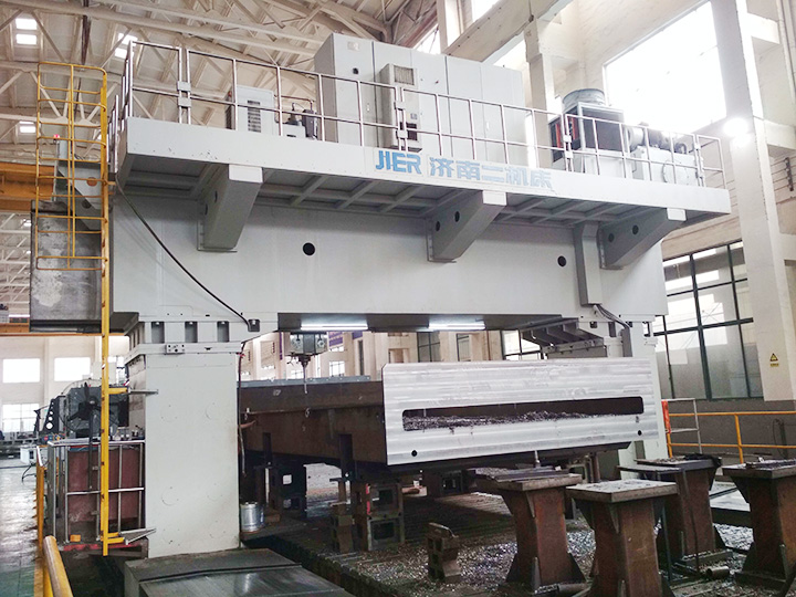
Design for Manufacturing is the discipline of designing parts so they can be produced at target cost, on target lead time, at target quality, using the available processes. The ten DFM rules — standard process, material selection, standardization, tolerance, internal radii, setup minimization, standard tooling, surface finish, inspection, and shop communication — are the foundation of a DFM pass. The mistakes that increase cost are the same mistakes that DFM is designed to prevent. The DFM review is a structured pass over the drawing before release. The result is a part that the shop can produce efficiently, the inspector can verify reliably, and the customer can use confidently. Yuqing's
CNC machine tool processing, structural parts, weldments, and mechanical parts capabilities are designed to reward DFM-optimized drawings and to provide feedback when drawings can be improved.
Frequently Asked Questions
What is the difference between DFM and DFT (Design for Testing)?
DFM is design for manufacturing; DFT is design for testing or inspection. Both are part of the broader DFX (Design for Excellence) framework. For custom CNC parts, DFM and DFT overlap heavily because the same features that drive manufacturing cost also drive inspection cost. A defensible design pass covers both.
When should DFM be applied in the design cycle?
DFM should be applied as early as possible. The earlier a DFM issue is caught, the cheaper it is to fix. A DFM issue caught in the concept phase can be fixed with a sketch change; a DFM issue caught in production requires a tooling change, a setup change, or a part rework.
Who is responsible for DFM in a custom CNC project?
The designer is responsible for engaging with the shop during the design phase. The shop is responsible for providing feedback on manufacturability. The project engineer is responsible for coordinating the DFM pass and ensuring that feedback is incorporated. DFM is a shared responsibility, not the designer's alone.
What is the cost of skipping DFM?
The cost of skipping DFM varies, but typical outcomes are 1.5× to 5× higher per-part cost, 2× to 4× longer lead time, and a higher scrap rate. The cost is paid every time the part is produced, so the cumulative cost over a program is significant.
What is the DFM review deliverable?
The DFM review deliverable is a list of drawing changes, with a justification for each change, the estimated cost impact, and the estimated lead time impact. The changes are tracked in a DFM log and signed off by the designer before the drawing is released.
How does DFM apply to weldments?
DFM for weldments adds a few specific considerations: access for the welding torch, joint design that is weldable without excessive distortion, machining stock that allows for weld shrinkage, and heat treatment coordination. The DFM review for a weldment typically includes a welding engineer in addition to the machining and quality engineers.
How does DFM apply to large structural parts?
Large structural parts (e.g., frames, bases, columns) have additional DFM considerations: the part must be machinable on the available equipment (e.g., floor-type boring), the workholding must support the part weight, the inspection must be feasible at the part scale, and the handling must be within the shop's crane capacity. DFM for large parts is often done in person with the shop's engineering team.
Can DFM be automated?
Some DFM checks can be automated (e.g., feature recognition, tolerance analysis, standard library comparison). Most DFM review, however, requires engineering judgment about function, manufacturing capability, and cost trade-offs. The best DFM practice combines automated checks with human review.
What is the relationship between DFM and standard parts?
DFM and standard parts are complementary. A drawing that uses standard catalog components (e.g., a standard fastener, a standard bushing) reduces custom manufacturing and inventory. A DFM pass should always consider whether a standard catalog part can replace a custom machined feature.
How often should the DFM rules be reviewed?
The DFM rules should be reviewed annually, or whenever a major change occurs in the shop's capability (new machine, new tooling, new process). The rules are a living document, not a one-time project.