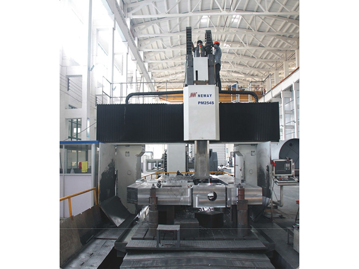
There is a point in size where the machining problem stops being about cutting and starts being about moving, holding and measuring. Machining a large component is mostly that second problem.
A 30-tonne casting cannot be nudged into position, cannot be re-clamped casually, and cannot be carried to the inspection room. Every decision around it — lifting, seating, clamping, measuring — has to be right the first time, because the cost of a second attempt is measured in crane hours and days.
Sizing the Job Before Anything Moves
Three numbers decide whether machining large components is possible at all, and all three should be confirmed in writing before the part is lifted:
• Envelope — the part must fit the machine's travel in X, Y and Z, with allowance for tool length and fixture height
• Weight — the table or floor loading must be rated for it, with margin
• Lifting points — the part must have identifiable, structurally sound points for slings or a spreader beam
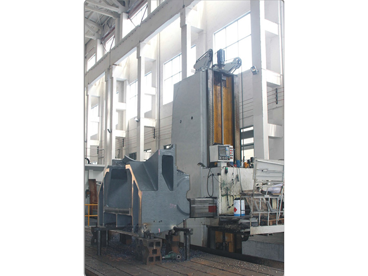
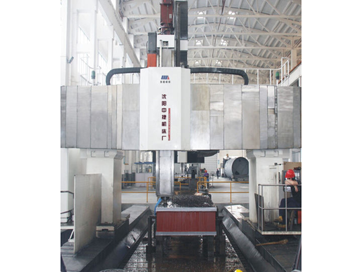
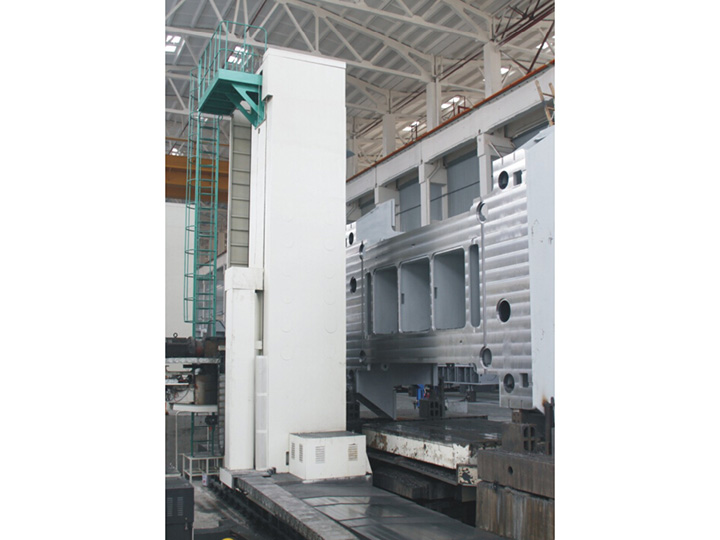
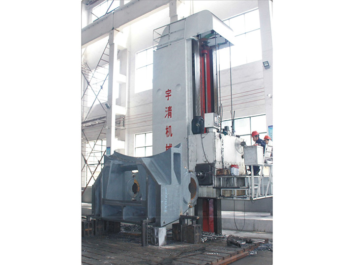
Yuqing's Φ160 floor-type boring and milling machine has a standard table of 2000 × 2500mm, optionally 3000 × 4000mm, with a load capacity up to 30 tonnes. Travel is up to 10000mm in X, 3000mm in Y, 2000mm in Z and 800mm in W, with extension available. The largest gantry machining centre carries a 6000 × 13000mm table with 3000mm of height. Overall machine weight on the floor-type unit is 65–80 tonnes, with an external footprint around 12000 × 4500 × 5000mm.
Lifting and Seating
Centre of Gravity and Sling Angles
Lifting a large component is a rigging operation, not a machining operation, and it has to be planned as one.
Centre of gravity. On an asymmetric casting or weldment, the centre of gravity is rarely where it looks. A part that tilts during the lift can swing into the machine, and a part that lands off-centre will need re-seating.
Sling angles. The load on each leg of a two-leg sling rises sharply as the included angle opens. Wide, low parts need a spreader beam rather than long slings.
Seating. The part must land on a stable, clean surface. On a machined table, swarf or a burr under one corner is enough to tilt the part and destroy the alignment before the first cut.
Jacking and shimming. Where the part's underside is rough, machined pads or shims establish a predictable three-point or four-point seat, which then becomes the basis for the clamping plan.
Clamping Without Distorting the Part
Five Clamping Rules
On a large component,
clamping force and part stiffness are in competition. Clamp too hard and the part deflects; release the clamps and it springs back, so the part you measured is not the part you shipped.
The practical rules:
1. Support under the load path. Place supports and clamps under the material that carries the cutting force, not in free space.
2. Distribute the force. Several moderate clamps beat two heavy ones, because the load per point is lower and the deflection is more even.
3. Clamp to a machined face where possible, so the contact is predictable.
4. Check after clamping. Measure a reference feature once the clamps are tightened; if it has moved, the clamping is distorting the part.
5. Re-check after releasing. On thin-wall or high-removal work, measure the free-state dimension as well as the clamped one.
The last point is the one that catches people. A bore that measures 0.02mm oversize in the machine and 0.02mm oversize out of it is fine. One that measures correct in the machine and changes on release is a clamping problem, not a machining problem.
Thermal Behaviour on a Large Component
On large work, temperature is a dimensional variable, not an environmental detail.
Steel expands by about 12 × 10⁻⁶ per °C. Across a 6-metre component, a 1°C change moves a feature by roughly 0.07mm — more than a typical finish tolerance. Across a 10-metre travel, the machine's own structure moves too.
Three compensations are standard on heavy machines:
• Thermal growth compensation — models spindle and axis growth and corrects the position
• Backlash compensation — matters more as travel length increases
• 3D volumetric compensation — corrects error across the full working volume instead of per axis
The workpiece side is managed by letting the part stabilise before finishing, keeping the workshop temperature stable, and stating the temperature at which dimensions are reported. On large components, a dimension without a stated temperature is an incomplete specification.
In-Process Measurement on a Large Part
You cannot carry a 20-tonne component to the inspection room, so measurement happens at the machine.
In-process measurement integrated with the CNC control checks tool wear, part orientation and dimensional accuracy while the part is still clamped and positioned. This is the mechanism that prevents the most expensive failure in heavy machining — discovering a 0.15mm error after the part has been unclamped, lifted and transported.
The measurement plan usually follows the machining sequence:
1. Measure after roughing to confirm the part is sitting where the program assumes
2. Re-datum if the roughing revealed a seating problem
3. Measure after semi-finishing to confirm remaining stock
4. Finish, then measure critical features in the clamped state
5. Release clamps and re-measure the features that distortion could affect
Final Metrology
Instruments and What They Prove
Final verification combines machine-integrated measurement with independent instruments:
|
Method |
What it verifies |
Where it is used |
|
In-process probing |
Position and stock during machining |
Roughing and semi-finishing stages |
|
2D / 3D laser measurement |
Large-scale geometry, flatness, alignment |
Long faces, large frames |
|
Coordinate measuring machine (CMM) |
Full-dimension verification with reported values |
Critical features, final acceptance |
|
Roughness testing |
Functional surface finish |
Sealing and sliding faces |
|
Hardness testing |
Heat treatment verification |
Wear surfaces |
|
UT / RT / MT |
Internal and surface weld quality |
Welded and cast components |
Yuqing's machine accuracy supports this work: positioning accuracy of ±0.015mm per 1000mm and repeat positioning accuracy of ±0.008mm on the floor-type machine, with bored hole roundness within 0.005mm. Spindle radial runout is held under 0.003mm and axial displacement under 0.002mm, on a forged alloy spindle that is carburised, quenched and precision ground, running on imported roller bearings assembled by constant-temperature cold fitting. Every machine completes a 72-hour no-load running test, full-stroke positioning accuracy testing and trial cutting before dispatch, with assembly inspection and accuracy calibration reports provided.
Handling After Machining
The risks of machining large components do not end when the cut finishes. A finished large component faces three more hazards before it reaches the customer:
• Damage during unloading — unprotected machined faces contacting slings or the floor
• Corrosion in transit — especially on machined steel surfaces in humid sea freight
• Distortion in storage — a long component supported at two points will sag over time
Yuqing applies damage-proof export packing with vacuum packaging, foam protection and wooden pallets for sea, air and land transport, meeting international logistics requirements. For long components, the pallet or support arrangement is designed to match the actual support points on the drawing.
Working With Yuqing Heavy Machinery
Changzhou Yuqing Heavy Industry Machinery Co., Ltd. has been machining and casting since 1989, operating from a 10,000m² facility in Xueyanqiao Town, Wujin District, Changzhou, Jiangsu, China. The company runs more than 30 machines, including gantry machining centres up to 6000 × 13000mm, Φ160 and Φ200 floor-type boring and milling machines, and a 5-metre vertical lathe, with more than 70 staff. It holds ISO certification, was recognised as a national high-tech enterprise in 2025, and serves customers in China, the United States, Japan, South Korea, India, Thailand, Finland and Germany.
Send your large component drawings, weights and lifting constraints to sales@czyqzg.com or call +86 13906152937.