Why Is Workholding Foundational to CNC Machining?
A CNC machine repeats its programmed path with high precision. The cutting tool follows the path with high accuracy. But the path is in the machine's coordinate system, not the workpiece's coordinate system. If the workpiece is not located accurately and repeatably, the path is correct but the part is wrong.
Workholding does three things:
Locates the workpiece in the correct position relative to the machine's coordinate system.
Clamps the workpiece rigidly enough to withstand cutting forces without movement or deflection.
Allows the part to be released after machining without damage and to be repositioned for additional operations.
Each of these functions must be engineered. A vise that is too small for the part will not clamp the corners. A clamp that is too tight will distort thin-wall features. A fixture that is not repeatable will produce parts that vary from blank to blank.
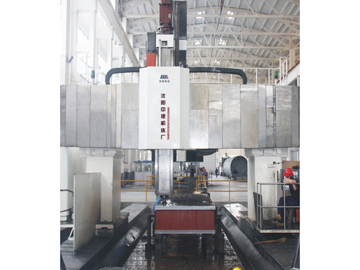
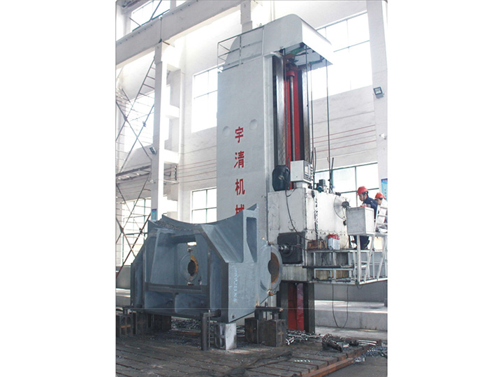
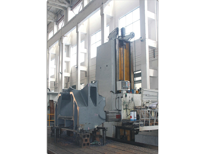
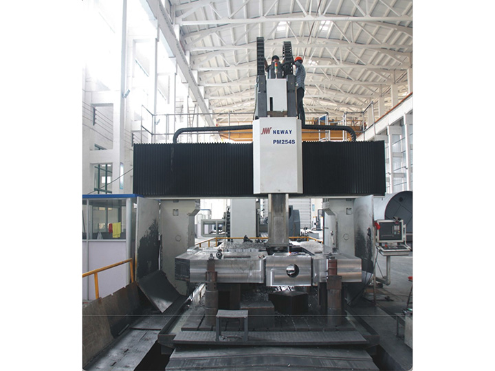
The CNC machine tool processing capability at Yuqing includes fixture design and build for both standard and custom parts.
What Are the Main Workholding Types?
|
Type |
Description |
Typical Application |
|
Machine vise |
Mechanical or hydraulic vise with fixed and movable jaws |
Rectangular parts, prismatic shapes |
|
Precision vise |
Ground vise with high parallelism and squareness |
Precision milling, tight tolerances |
|
Chuck (3-jaw, 4-jaw, 6-jaw) |
Self-centering or independent jaw chuck |
Cylindrical parts (turning) |
|
Collet chuck |
Precision collet for round parts |
High-precision turning, small parts |
|
Magnetic chuck |
Permanent or electromagnetic |
Ferromagnetic flat parts |
|
Vacuum chuck |
Vacuum plate with seal |
Flat non-ferrous parts, thin sheets |
|
Custom fixture |
Designed and built for a specific part |
Complex geometry, high repeatability |
|
Tombstone / pallet |
Multi-sided fixture for production runs |
Production cells, batch machining |
|
Indexer / trunnion |
Rotational axis for 4th and 5th axis work |
Multi-sided machining, complex parts |
|
Fixture plate (sub-plate) |
Standard plate with hole pattern for modular clamping |
Quick change-over, low-volume runs |
The selection depends on the part geometry, the production volume, the required accuracy, and the operator skill.
How Is the Vise Selected?
The vise is the most common workholding for prismatic parts. Selection considerations:
Jaw width: must exceed the part's clamping dimension. A vise with 150 mm jaws can clamp parts up to about 130 mm wide.
Jaw opening: must accommodate the part's largest dimension in the clamping direction.
Clamping force: must be sufficient to prevent movement but not so much that it distorts the part.
Jaw type: soft jaws (machinable to the part's profile) for custom parts, hard jaws (standard) for production runs of similar parts.
Vise type: precision vise for tight tolerances, standard vise for general purpose.
A precision vise (e.g., 0.01 mm parallelism, 0.01 mm squareness) is essential for finishing passes that require tight dimensional control. A standard vise may be adequate for roughing.
What Is Soft Jaw Machining?
Soft jaws are aluminum or steel jaws that are machined in place to match the part's profile. The procedure:
Mount the soft jaws in the vise.
Place the part in the jaws, against a fixed stop (or against the movable jaw's open position).
Indicate the part to the vise body.
Clamp the jaws onto the part.
Machine the jaws to the part's profile (typically 0.5–1 mm of material removed).
Soft jaws provide:
Accurate location: the machined profile matches the part exactly.
High clamping force: the jaws can be tightened without damaging the part.
Repeatable positioning: the part seats in the same profile each time.
Soft jaws are standard for production runs where the part geometry is consistent. They are not practical for one-off parts (the time to machine the jaws exceeds the time to machine the part).
What Is the 3-2-1 Locating Principle?
The 3-2-1 principle defines the minimum number of contact points to fully constrain a rigid body:
3 points: define a primary plane (constrain 3 degrees of freedom: rotation about two axes, translation along one axis).
2 points: define a secondary plane perpendicular to the primary (constrain 2 more degrees).
1 point: define a tertiary plane perpendicular to both (constrain the last degree).
More than 3+2+1 contact points is over-location, which creates redundant constraints that must be satisfied simultaneously. Over-location prevents non-ideal parts from seating and creates stress in the fixture.
A well-designed fixture uses exactly 3+2+1 contact points for each part. The contacts are placed far apart for stability, on machined (not rough) surfaces for accuracy, and at features that exist on every blank (not at features that vary).
How Is Clamping Force Determined?
Clamping force must overcome the cutting force without moving the part or distorting it:
F_clamp ≥ F_cut × safety_factor / friction_coefficient
Typical values:
Milling: cutting force 500–3000 N; clamp force 5–30 kN; safety factor 2–3.
Turning: cutting force 200–2000 N; clamp force 3–20 kN; safety factor 2–3.
Drilling: thrust force 100–1000 N per mm of drill diameter; clamp force 3–10 kN; safety factor 2–3.
A clamp that applies too much force distorts thin-wall features and may shift the part. A clamp that applies too little force allows the part to move during cutting, producing out-of-tolerance dimensions or broken tools.
Hydraulic and pneumatic clamps provide consistent, adjustable force. Mechanical clamps (screw, cam) provide manual force that depends on the operator.
How Are Thin-Wall Parts Held?
Thin-wall parts (less than 1 mm wall, or aspect ratio > 20:1) are particularly sensitive to clamping distortion. Strategies:
Distributed clamping: multiple clamps at small intervals rather than one large clamp.
Backing: a sacrificial backing piece that supports the thin wall from the inside during cutting.
Vacuum chuck: applies uniform pressure to the back side without contact on the thin wall.
Fixture with conforming jaws: jaws machined to match the part's outer profile.
Reduced cutting force: lower feed, sharper tools, multiple light passes instead of one heavy pass.
A thin-wall part clamped with too much force will spring back after release, producing out-of-tolerance dimensions. The fixture design must address this from the start.
What Are Modular Fixturing Systems?
Modular fixturing systems use standard components (bases, columns, clamps, locating pins) to build a fixture quickly for a specific part. The major systems (5-Axis, Bluco, Carr Lane, Lang) provide consistent locating accuracy and quick change-over.
Modular systems are well suited to:
Low-volume production runs.
Parts that change frequently.
Rapid prototyping and process development.
Modular systems are less efficient for high-volume production where a dedicated custom fixture is faster to load and unload.
What Is a Tombstone and Pallet System?
A tombstone is a vertical fixture with multiple sides, each holding a different part or operation. A pallet is a horizontal fixture plate with locating points for one or more parts. Tombstones and pallets allow a fixture to be loaded outside the machine while the machine is cutting another fixture, increasing spindle utilization.
Tombstones and pallets are standard in production cells:
HMC tombstone: mounted on the HMC's trunnion, allowing multiple faces to be machined in one setup.
VMC pallet: mounted on the VMC table, loaded on a pallet pool outside the machine.
Custom tombstones: designed for a specific part family.
The decision to use a tombstone or pallet system is based on production volume, change-over frequency, and capital cost.
How Is Fixture Repeatability Verified?
Fixture repeatability is verified by:
Loading and clamping a part in the fixture.
Indicating the part to the machine coordinate system (typically a probe or a precision indicator).
Recording the position.
Unloading, reloading, and re-indicating.
Calculating the variation across 5–10 cycles.
Typical fixture repeatability:
Vise with soft jaws: 0.005–0.020 mm.
Dedicated fixture: 0.010–0.050 mm.
Modular fixture: 0.020–0.100 mm.
Indexer / trunnion: 0.010–0.050 mm (rotational accuracy).
A fixture that does not repeat is a fixture that requires rework before production can begin.
How Is the Datum Scheme Established?
The datum scheme is the set of features on the part that are used for location. The datum scheme on the fixture must match the datum scheme on the drawing (the part's functional references).
If the drawing specifies Datum A on the bottom face, Datum B on a side face, and Datum C on a hole, the fixture must provide:
A primary locator on the bottom face.
A secondary locator on the side face.
A tertiary locator in the hole.
A fixture that locates the part differently from the drawing creates parts that are correct in the machine's coordinate system but wrong in the assembly's coordinate system.
What Is the Role of Fixture Plate and Sub-Plate?
A fixture plate is a machined plate with locating features and clamping points. A sub-plate is a smaller plate that mounts to the machine table and accepts multiple fixture plates.
The use of fixture plates allows:
Standardized mounting to the machine table.
Quick change-over of fixtures for different parts.
Off-line setup of fixtures while the machine is running.
Reduced setup time per part.
For production cells, fixture plates are essential. For low-volume runs, the time investment may not pay back.
How Are Vacuum Chucks Used?
A vacuum chuck holds the workpiece by applying vacuum through small holes in a fixture plate. A gasket or seal around the part prevents vacuum leakage.
Vacuum chucks are used for:
Flat non-ferrous parts (aluminum, plastic, composites).
Thin sheets that cannot be clamped mechanically.
Parts with delicate surfaces that would be damaged by mechanical clamping.
Vacuum chuck limitations:
Requires a sealed surface (or a gasket).
Limited holding force (typically 0.5–1.0 bar pressure differential).
Not suitable for heavy cutting forces.
Requires a vacuum pump with sufficient capacity.
What Is Magnetic Chucking?
Magnetic chucks use permanent magnets or electromagnets to hold ferromagnetic workpieces. They are standard for:
Surface grinding of steel parts.
Milling of thin steel plates.
Operations where mechanical clamping is impractical.
Magnetic chuck limitations:
Works only on ferromagnetic materials (steel, iron; not stainless or aluminum).
Holding force depends on part thickness and surface condition.
Cannot hold non-flat parts without a custom pole piece.
How Is the Fixture Maintained?
Fixture maintenance is often overlooked but is essential for consistent production:
Cleaning: chips, coolant, and debris must be removed after each shift.
Inspection: locating surfaces, clamps, and locating pins must be inspected for wear at defined intervals.
Repair: damaged clamps or locating surfaces must be repaired or replaced before they affect production.
Calibration: fixtures used for tight tolerance work should be calibrated periodically (e.g., annually) against a reference.
Documentation: each fixture should have a record of use, maintenance, and calibration.
A shop that maintains its fixtures produces consistent parts. A shop that neglects fixtures produces drifting parts.
How Is Workholding Chosen for Specific Operations?
Different operations require different workholding:
|
Operation |
Typical Workholding |
Notes |
|
Face milling of large plates |
Magnetic chuck or vacuum chuck |
Distributed clamping needed |
|
Pocket milling of blocks |
Machine vise with soft jaws |
Match profile to block |
|
Drilling of hole patterns |
Fixture plate with drill bushings |
Bushings guide the drill |
|
Tapping of threads |
Fixture with tension/compression tap holder |
Tap holder compensates for spindle error |
|
Boring of large bores |
Fixture with boring bar support |
Bar needs support to avoid chatter |
|
4th-axis machining |
Indexer or trunnion |
Locating features must be accessible |
|
5th-axis machining |
Trunnion with secondary axis |
Complex fixturing, often custom |
The operation determines the workholding approach, not the other way around.
What Is the Cost of Workholding?
Workholding cost is part of the part cost, especially for low-volume production:
|
Workholding Type |
Cost Range |
|
Standard vise |
200–1,000 |
|
Precision vise |
1, 000–5,000 |
|
Soft jaws (custom machined) |
50–300 per set |
|
Custom fixture |
500–10,000+ |
|
Modular fixture |
1, 000–20,000 for components |
|
Tombstone with multiple fixtures |
5, 000–50,000+ |
|
Vacuum chuck |
500–5,000 |
|
Magnetic chuck |
500–5,000
|
For a one-off part, the workholding cost may exceed the part's machining cost. For high-volume production, the fixture cost is amortized over many parts.
What Is the Trend in Workholding Technology?
The trend is toward:
Smart fixtures: with sensors that detect part presence, clamping force, and temperature.
Zero-point clamping systems: for fast change-over with repeatable accuracy.
Additive-manufactured fixtures: conformal cooling, optimized stiffness, fast iteration.
Hydraulic and electric clamping: for consistent force independent of operator skill.
Vision-guided loading: for automated loading of blanks into fixtures.
The trend supports the same objective: shorter setup time, fewer operator errors, and more consistent parts.
Conclusion
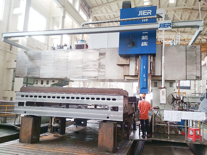
Workholding and fixture design are the engineering disciplines that locate and clamp the workpiece accurately and rigidly during cutting. The fixture is engineered to match the part's datum scheme, to apply the correct clamping force, and to be repeatable across the production run. The
CNC machine tool processing and structural parts processing capabilities at Yuqing include fixture design for both standard and custom parts; engineers should specify the fixture requirements on the drawing so the shop can plan the workholding approach.
Frequently Asked Questions
What is the most common workholding mistake?
Over-location — providing too many contact points so that normal dimensional variation prevents the part from seating. The operator then forces the part into the fixture, creating stress and producing inconsistent parts.
How much clamping force is enough?
Clamping force must exceed the cutting force divided by the friction coefficient, with a safety factor of 2–3. Too much force distorts the part; too little allows movement during cutting.
When should soft jaws be used?
Soft jaws should be used for custom or low-volume production, for parts with non-standard geometry, and for tight-tolerance finishing where repeatability is critical. They are not necessary for roughing or for parts that match standard vise jaw geometry.
What is the difference between a fixture plate and a tombstone?
A fixture plate is flat and mounts horizontally. A tombstone is vertical with multiple faces, each holding a different fixture. Tombstones are used on HMCs to machine multiple parts in one setup.
How are thin-wall parts held without distortion?
By using distributed clamping, backing pieces, vacuum chucks, or conforming jaws that match the part's profile. Light cuts and sharp tools also reduce distortion.
How is fixture repeatability measured?
By loading and indicating the same part 5–10 times, and calculating the variation in position. The result is compared to the part's tolerance budget; the fixture should consume only a fraction of the total tolerance.
What is the cost of a custom fixture?
Custom fixtures range from a few hundred dollars for a simple soft-jaw setup to tens of thousands for a complex tombstone with multiple pallets. The cost is amortized over the production volume.
How is fixture maintenance documented?
Each fixture should have a record card (physical or digital) showing each use, each inspection, and each repair. The card is reviewed periodically and is the basis for fixture replacement.
What is the difference between a fixture and a jig?
A fixture holds the part in a fixed position for machining. A jig also guides the cutting tool (e.g., a drill jig with bushings). Most CNC workholding is fixturing; jigs are more common in manual machining.
How is vacuum chucking used for thin parts?
A vacuum chuck applies uniform pressure to the back of the part through a sealed fixture plate. The holding force is limited (typically < 1 bar differential), so vacuum chucks are used for light cutting or for holding while a different operation does the heavy cutting.