Why Is Tooling the Largest Source of Variability in CNC Machining?
A CNC machine repeats its programmed path with high precision. The cutting tool, however, wears, deflects, and changes geometry over its life. The tool is the element that introduces variation into the process. Tool wear shifts dimensions, degrades surface finish, increases cutting forces, and can damage the part or the machine if left unchecked.
A shop with disciplined tooling management produces consistent parts with predictable cycle times. A shop without it produces parts that drift over a production run, requires rework, and occasionally crashes. The difference is the tooling program.
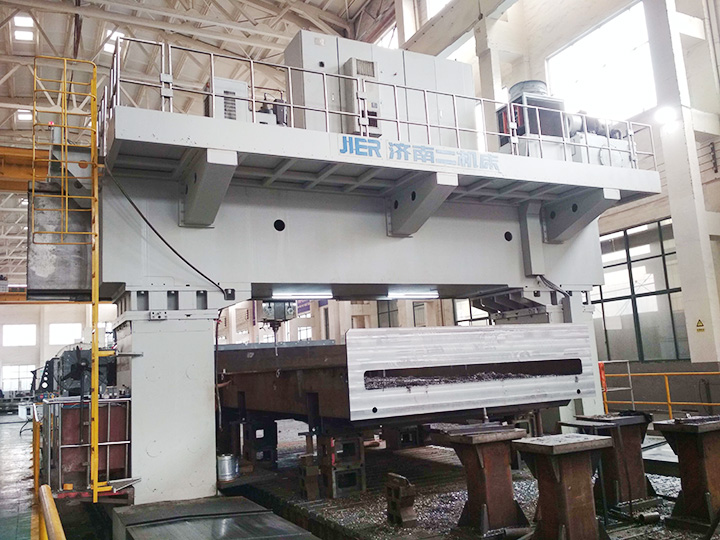
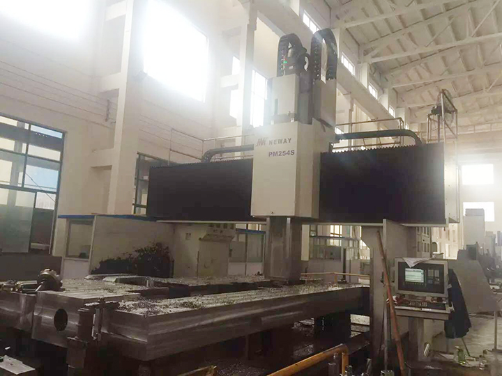
The CNC machine tool processing and floor-type boring and milling machine capabilities at Yuqing are supported by a tooling program that pairs standard inserts with manufacturer-recommended parameters.
What Are the Tool Materials?
|
Tool Material |
Composition |
Strengths |
Limitations |
|
High-speed steel (HSS) |
Steel with W, Mo, V, Co |
Tough, low cost, easy to regrind |
Slower speeds, shorter life |
|
Cobalt HSS |
HSS + 5–10% Co |
Better heat resistance than HSS |
Still slower than carbide |
|
Uncoated carbide |
WC + Co binder |
Hard, wear resistant, fast |
Brittle, can chip |
|
Coated carbide |
Carbide + TiN, TiAlN, AlCrN coating |
Higher speeds, longer life |
Coating wear limits life |
|
Cermet |
TiC + Ni binder |
High wear resistance, fine finish |
Brittle, limited chipping resistance |
|
Ceramic (Al2O3, SiAlON) |
Alumina-based |
High speeds for cast iron, Ni alloys |
Brittle, not for steel |
|
CBN (cubic boron nitride) |
Cubic BN bonded |
Hard, for hardened steel (HRC > 50) |
Very expensive, brittle |
|
PCD (polycrystalline diamond) |
Diamond particles bonded |
Best for aluminum, composites, abrasive plastics |
Cannot machine ferrous materials |
The choice is driven by the workpiece material, the required speed, the required life, and the cost per part. Aluminum and engineered plastics favor PCD or uncoated carbide. Steels favor coated carbide. Hardened steels (HRC > 50) require CBN. High-temperature alloys (Inconel, titanium) favor ceramic or advanced coated carbide.
How Is Cutting Speed Selected?
Cutting speed (Vc) is the surface speed at the cutting edge, in meters per minute (m/min) or surface feet per minute (sfm). It is the primary variable in tool life.
|
Workpiece Material |
HSS Vc (m/min) |
Carbide Vc (m/min) |
PCD/Ceramic Vc (m/min) |
|
Mild steel (1018) |
25–35 |
100–180 |
— |
|
Alloy steel (4140 annealed) |
20–30 |
80–150 |
— |
|
Stainless steel (304) |
15–25 |
60–120 |
— |
|
Tool steel (HRC 30) |
10–20 |
50–80 |
80–120 (ceramic) |
|
Hardened steel (HRC 60) |
— |
30–60 (CBN) |
80–150 (CBN) |
|
Cast iron |
20–30 |
80–150 |
200–400 (ceramic) |
|
Aluminum (6061) |
80–150 |
300–600 |
600–1500 (PCD) |
|
Brass |
50–100 |
150–300 |
400–800 (PCD) |
|
Titanium (Ti-6Al-4V) |
10–20 |
30–60 |
50–100 |
|
Engineering plastic (Delrin) |
100–200 |
200–400 |
400–1000 (PCD) |
Vc is held constant; the spindle speed (RPM) is adjusted based on the cutter diameter. A drawing that specifies a small-diameter cutter in a tough material will produce a high RPM and may exceed the machine's spindle limit — the parameter selection must respect both the cutting physics and the machine's capability.
How Is Feed Rate Selected?
Feed rate (f) is the linear advance of the tool per revolution (mm/rev or in/rev for turning) or per tooth (mm/tooth or in/tooth for milling). It is the primary variable in chip load, which affects surface finish and tool life.
|
Workpiece Material |
Milling fz (mm/tooth) |
Turning f (mm/rev) |
|
Aluminum |
0.05–0.30 |
0.10–0.50 |
|
Mild steel |
0.05–0.20 |
0.10–0.40 |
|
Stainless steel |
0.04–0.15 |
0.08–0.25 |
|
Titanium |
0.03–0.10 |
0.05–0.20 |
|
Hardened steel (HRC > 50) |
0.02–0.08 |
0.05–0.15 |
|
Cast iron |
0.05–0.20 |
0.10–0.30 |
Feed rate is the most consequential variable for tool life. Increasing feed by 50% can reduce tool life by 80% (Taylor's tool life equation). The shop must select a feed that balances productivity against tool life.
How Is Depth of Cut Selected?
Depth of cut (ap, ae) is the radial and axial engagement of the tool with the workpiece. It affects cutting forces, tool deflection, and the number of passes required.
|
Pass Type |
Typical ap (mm) |
Typical ae (mm) |
|
Heavy roughing |
1× D (full cutter diameter) |
0.5× D |
|
Light roughing |
0.5× D |
0.25× D |
|
Semi-finishing |
0.25× D |
0.10× D |
|
Finishing |
0.05–0.10× D |
0.02–0.05× D
|
A heavier depth of cut reduces the number of passes but increases cutting force and tool deflection. A lighter depth of cut improves accuracy and surface finish but increases cycle time. The shop selects the strategy based on the part's geometry, the machine's rigidity, and the tool's capability.
How Is Coolant Used?
Coolant serves three purposes: removing heat from the cutting zone, flushing chips from the cut, and lubricating the tool-workpiece interface.
|
Coolant Type |
Application |
Notes |
|
Flood coolant (water-based emulsion) |
General purpose for steel, stainless |
Cost-effective, requires concentration control |
|
Flood coolant (synthetic) |
Aluminum, precision machining |
Cleaner, longer life |
|
High-pressure coolant (≥ 70 bar) |
Deep holes, tough materials |
Better chip evacuation, longer tool life |
|
Minimum quantity lubrication (MQL) |
Some aerospace, dry machining |
Low consumption, environmental benefit |
|
Through-tool coolant |
Drilling, deep pockets, medical |
Improved chip evacuation |
|
Cryogenic (LN2) |
Titanium, Inconel |
Experimental, very expensive |
For most custom CNC work, flood coolant with water-based emulsion is standard. High-pressure or through-tool coolant is added for deep-hole drilling, tough materials, or long tool life requirements. The coolant concentration, pH, and contamination must be monitored to prevent corrosion and bacterial growth.
How Is Tool Life Estimated?
Tool life is estimated from Taylor's equation or from manufacturer data:
VT^n = C
where V is cutting speed, T is tool life in minutes, n is the Taylor exponent (typically 0.2–0.4 for carbide in steel), and C is a constant that depends on the workpiece material, tool material, and cutting conditions.
In practice, shops use manufacturer-recommended starting parameters and adjust based on observed tool wear. A tool that achieves 30 minutes of life in production is replaced at 25 minutes (planned life) to avoid running into the wear zone where part quality degrades.
For high-value parts (aerospace, medical), the tool is replaced even earlier to ensure zero risk of failure.
What Are the Tool Wear Modes?
|
Wear Mode |
Cause |
Effect |
Mitigation |
|
Flank wear |
Abrasion on the clearance face |
Dimensional drift, increasing cutting force |
Speed/feed adjustment, coating selection |
|
Crater wear |
Chemical reaction at high temperature |
Tool geometry changes |
Lower speed, better coating |
|
Built-up edge (BUE) |
Workpiece material welding to the tool |
Poor finish, sudden release |
Higher speed, sharper edge, coolant |
|
Chipping |
Mechanical impact, vibration |
Sudden geometry loss |
Reduce depth of cut, increase rigidity |
|
Fracture |
Excessive force, brittle tool |
Catastrophic tool failure |
Reduce engagement, check holder |
|
Thermal cracking |
Thermal cycling |
Random cracks on cutting edge |
Use coolant properly, reduce speed
|
A shop that monitors tool wear visually and dimensionally can identify the wear mode and take corrective action before the part is affected.
How Is Tool Wear Compensated?
Tool wear compensation adjusts the tool's offset based on measured wear. Modern CNC machines support:
Length wear compensation: adjusts the tool length offset by the measured wear.
Diameter wear compensation: adjusts the tool diameter offset, typically used for finishing passes.
Automatic wear compensation: in-process measurement (touch probe, laser) triggers automatic offset adjustment.
For long production runs, automatic compensation is the standard. For short custom runs, manual compensation based on a periodic dimensional check is sufficient.
How Is Tool Management Organized?
A disciplined tool management program includes:
Tool list: every tool used on the part, with manufacturer, grade, geometry, and expected life.
Tool assembly record: holder, collet, balance, runout.
Tool life tracking: time or part count since tool change, wear condition.
Tool change procedure: how to change, what to inspect, how to re-set the offset.
Tool storage: clean, organized, identified (often with bar codes or RFID).
Tool regrinding program: which tools are reground, by whom, with what inspection.
A shop that has this discipline produces consistent parts. A shop that does not produces inconsistent parts and surprises.
How Are Inserts Selected?
Indexable inserts (the cutting tips in a milling cutter or a turning holder) are selected by:
Geometry: the insert shape (square, round, triangular, diamond) determines the strength and the range of applications.
Grade: the carbide grade and coating determine the wear resistance and the recommended workpiece materials.
Nose radius: the corner radius affects surface finish and tool life (larger radius = better finish, longer life, more sensitive to chatter).
Chipbreaker: the geometry on the top of the insert that controls chip formation and evacuation.
The shop chooses based on the material, the operation (roughing or finishing), the desired finish, and the machine's capability.
What Is the Effect of Machine Rigidity?
Machine rigidity is the ability of the machine to resist deflection under cutting force. It is determined by the machine design, the spindle, the tool holder, and the workpiece fixturing.
A rigid setup can take heavy cuts at high feeds. A non-rigid setup must take lighter cuts at slower feeds, or it will chatter (vibrate, producing poor finish and shortened tool life).
The floor-type boring and milling machine at Yuqing (note: that URL is from a different site — for Yuqing, see equipment) is one example of a highly rigid machine designed for heavy-duty work. The choice of machine must match the part's requirements.
How Are Tool Holders Selected?
The tool holder is the interface between the spindle and the cutting tool. Common types:
|
Holder |
Application |
Runout |
Notes |
|
ER collet |
General purpose |
10–20 µm |
Versatile, limited balance |
|
Hydraulic chuck |
High precision |
3–5 µm |
Best for finishing |
|
Shrink-fit |
High rigidity |
3 µm |
Best for heavy roughing |
|
Side-lock |
Simple, rigid |
5–10 µm |
For drills and taps |
|
End mill holder |
General milling |
5–10 µm |
Set screw |
|
Tap holder |
Tapping |
— |
Tension/compression for tension control |
The holder choice affects tool life, surface finish, and dimensional accuracy. A high-precision holder (hydraulic or shrink-fit) is worth the cost for finishing operations and for materials that work-harden.
What Is the Trend in Tooling Technology?
The trend is toward:
Higher-feed insert geometries that reduce cycle time without sacrificing tool life.
Advanced coatings (AlCrN, TiSiN, nanocomposite) that extend life in tough materials.
Cryogenic and MQL systems that reduce coolant consumption.
Digital tool management with RFID tracking and predictive replacement.
Additive-manufactured tool bodies (conformal cooling channels, optimized stiffness).
AI-driven parameter optimization that adjusts feed and speed based on real-time cutting force.
The trend supports the same objective: more parts per tool, more consistent quality, and lower cost per part.
Conclusion
Tooling selection and tool life management are the disciplines that determine the consistency, cost, and lead time of CNC machined parts. The shop selects the tool material, the geometry, and the cutting parameters to match the workpiece, monitors tool wear, replaces tools on a planned schedule, and records the results. The
CNC machine tool processing and equipment capabilities at Yuqing are supported by a documented tooling program that delivers consistent quality across production runs.
Frequently Asked Questions
What is the most common cause of tool failure?
Excessive cutting force due to over-aggressive parameters (speed, feed, or depth of cut) is the most common cause. The tool breaks or chips when the force exceeds the tool's strength.
How is cutting speed calculated from RPM?
Vc = π × D × N / 1000, where Vc is cutting speed in m/min, D is cutter diameter in mm, and N is spindle speed in RPM. To find N for a target Vc, rearrange: N = Vc × 1000 / (π × D).
How is tool life measured on the shop floor?
By the number of parts machined, by the time since the tool was installed, or by visual inspection of the wear land. Modern CNC machines can also monitor cutting force or acoustic emission and signal when a tool is worn.
What is the difference between coated and uncoated carbide?
Coated carbide has a thin ceramic coating (TiN, TiAlN, AlCrN) applied by PVD or CVD. The coating reduces friction, increases wear resistance, and allows higher cutting speeds. Uncoated carbide is preferred for aluminum and for applications where the coating might chemically react with the workpiece.
What is chatter?
Chatter is self-excited vibration during cutting. It produces a poor surface finish, accelerated tool wear, and noise. Chatter is controlled by reducing depth of cut, changing speed, increasing rigidity (better holder, better fixturing), or using a variable-pitch cutter.
Can tooling be reground?
Yes. HSS tooling is commonly reground. Carbide inserts are typically not reground (the cost of regrinding exceeds the cost of a new insert), but solid carbide end mills can be reground by specialized shops. The regrinding must be to the original geometry and inspected before reuse.
What is the relationship between depth of cut and tool life?
Depth of cut has a smaller effect on tool life than speed or feed, but a larger effect on cutting force. Doubling the depth of cut doubles the cutting force (and the deflection), but reduces tool life by only 10–20%.
How is tool balance important?
An unbalanced tool vibrates at high RPM, producing poor surface finish, reduced tool life, and accelerated spindle bearing wear. Tool balance is especially critical for high-speed spindles (>10,000 RPM).
How is tool life for a specific insert determined?
The manufacturer publishes recommended starting parameters and expected tool life for each insert in each workpiece material. The shop uses these as a starting point and adjusts based on observed wear. A more aggressive application may reduce life; a more conservative application may extend it.